Difference between revisions of "Aqua-Sim-NG multichannel MAC implementation"
(Created page with "== Multichannel MAC implementation == * new <code>aqua-sim-mac-multichannel</code> module: Modified <code>TxProcess</code> and <code>RecvProcess</code> methods of the <code>...") |
|||
| Line 45: | Line 45: | ||
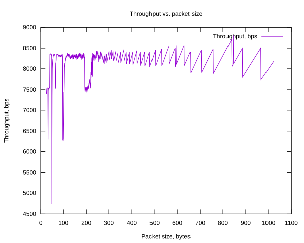
The throughput was measured, depending on varying packet length. The result is plotted on Fig.1. | The throughput was measured, depending on varying packet length. The result is plotted on Fig.1. | ||
| − | [[File: | + | [[File:throughput_1_channel.png]] |
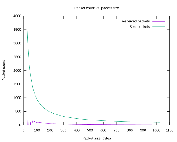
Corresponding sent/received packet count is illustrated on Fig.2. | Corresponding sent/received packet count is illustrated on Fig.2. | ||
| − | [[File:https://github.com/dugdmitry/aqua-sim-ng/blob/master/ | + | [[File:packet_count_1_channel,png]] Fig.2 |
| + | |||
| + | |||
| + | === 2-nd test === | ||
| + | |||
| + | During the simulation, various channels were used in the following “round-robin” way: | ||
| + | |||
| + | * 1_packet: channel_1 (10kHz) | ||
| + | * 2_packet: channel_2 (13kHz) | ||
| + | * 3_packet: channel_3 (16kHz) | ||
| + | * 4_packet: channel_4 (19kHz) | ||
| + | * 5_packet: channel_5 (22kHz) | ||
| + | * 6_packet: channel_6 (25kHz) | ||
| + | * 7_packet: channel_7 (28kHz) | ||
| + | * 8_packet: channel_8 (31kHz) | ||
| + | * 9_packet: channel_9 (34kHz) | ||
| + | * 10_packet: channel_11 (37kHz) | ||
| + | * 11_packet: channel_1 (10kHz) | ||
| + | * …. etc. | ||
| + | |||
| + | The throughput is plotted on Fig.3. | ||
| + | |||
| + | [[File:throughput_n_channels,png]] Fig.3 | ||
| + | |||
| + | Corresponding sent/received packet count is illustrated on Fig.4. | ||
| + | |||
| + | [[File:packet_count_n_channels.png]] Fig.4 | ||
| + | |||
| + | Code of simulation script can be found here: | ||
| + | |||
| + | [[https://github.com/dugdmitry/aqua-sim-ng/blob/master/examples/multichannel_mac_example.cc]] | ||
Revision as of 06:09, 8 August 2018
Multichannel MAC implementation
- new
aqua-sim-mac-multichannelmodule:
Modified TxProcess and RecvProcess methods of the AquaSimMac base class. Added channel division on N number of subchannels, depending on given bandwidth. By default, the following bandwidth is used and the following subchannels are created:
- bandwidth: 10 - 40 kHz
- step frequency: 3 kHz
- N of subchannels: 10
The following channel_id:frequency map is generated:
<channel_1 : 10 kHz>, <channel_2 : 13 kHz>, …, <channel_10 : 37 kHz>
- modified
aqua-sim-phy-cmnmodule:
Modified recv() method of AquaSimPhyCmn class, which is used for both transmission and reception of the scheduled packet. The modified recv() method has a new argument - frequency, and is executed by upper multichannel-mac module, depending on the selected channel_id.
- modified
aqua-sim-channelmodule:
Modified SendUp() method of AquaSimChannel class. Now this method gets a frequency value of the incoming packet, using AquaSimPacketStamp class and inserts it into the ::Recv() method of the AquaSimPhyCmn upon execution in the Scheduler.
Initial tests
For the initial tests the following simulation scenario was used:
“node_1 (sender)” <— 10m distance —> “node_2 (sink)”
The following stack was used on both nodes: - OnOffApplication — OffTime: 0, OnTime: 1 - Routing — Dummy (for MAC layer testing) - MultichannelMac — default bandwidth (10 - 40 kHz), 10 subchannels, 3kHz frequency step - PhyCmn — modified PhyCmn module
Some other parameters: - Simulation time: 10 seconds - Transmission range: 100 meters (for Phy module) - Distance: 10 meters (Mobility model)
In all tests a throughput was measured by defining an application data rate, higher than possible capacity of the given channel:
80 kbps dataRate parameter of OnOffApplication. Thus, the throughput was measured by counting a total amount of received packets:
throughput = total_received_packets * packet_size * 8 / 10, [bps]
where: 10 - simulation time, seconds.
1-st test
A single channel was used during entire simulation. - channel_id: 1, frequency: 10 kHz.
The throughput was measured, depending on varying packet length. The result is plotted on Fig.1.
Corresponding sent/received packet count is illustrated on Fig.2.
File:Packet count 1 channel,png Fig.2
2-nd test
During the simulation, various channels were used in the following “round-robin” way:
- 1_packet: channel_1 (10kHz)
- 2_packet: channel_2 (13kHz)
- 3_packet: channel_3 (16kHz)
- 4_packet: channel_4 (19kHz)
- 5_packet: channel_5 (22kHz)
- 6_packet: channel_6 (25kHz)
- 7_packet: channel_7 (28kHz)
- 8_packet: channel_8 (31kHz)
- 9_packet: channel_9 (34kHz)
- 10_packet: channel_11 (37kHz)
- 11_packet: channel_1 (10kHz)
- …. etc.
The throughput is plotted on Fig.3.
File:Throughput n channels,png Fig.3
Corresponding sent/received packet count is illustrated on Fig.4.
Code of simulation script can be found here:
[[1]]

